Urea prills
Nitrogen source with verified size and flowability
Organizes dosing, dissolution, filtration, storage and filling around the required liquid or soluble fertilizer formulation.
Start with material condition, product specification and operating plan before selecting equipment.
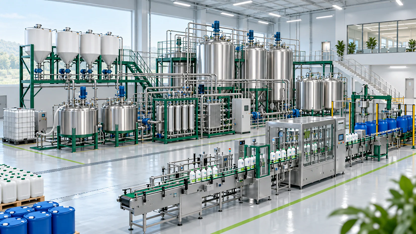
Published ranges support planning; final specifications follow the material, site and local-standard review.
Each material card combines the project requirement with a realistic visual reference.
Nitrogen source with verified size and flowability
Qualified compound fertilizer granules or nutrient base
Phosphate rock, SSP base or phosphate intermediates
MOP, SOP or compatible potassium salts
Measure free water and seasonal variation.
Confirm size, lumps, fibers and abrasiveness.
Identify stones, metal, plastics or insolubles.
Review caking, odor, flow and biological stability.
The line is configured backward from the required product and packaging standard.
Formula concentration, clarity, stability and filling format
Representative material reference. Replace with an approved finished-product photograph.Every stage is sized against its inlet, outlet and recycle duty.
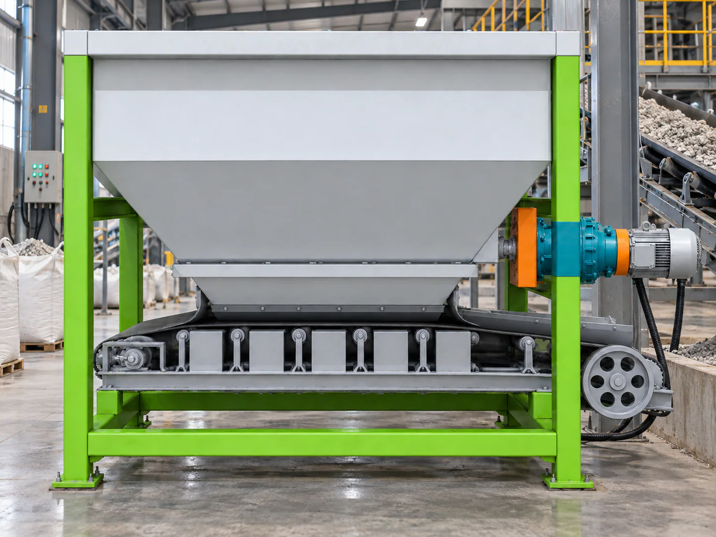
Protect the next process stage

Protect the next process stage
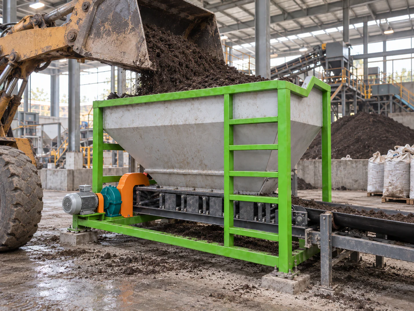
Protect the next process stage

Weigh and prepare approved product for dispatch
The final throughput is limited by the complete mass balance—including moisture change, recycle, storage buffers and packaging—not one machine’s nominal number.
Open each machine page for its role and selection boundary.
Meters, buffers or homogenizes materials to maintain stable recipe control and line flow.
View details →Meters, buffers or homogenizes materials to maintain stable recipe control and line flow.
View details →Meters, buffers or homogenizes materials to maintain stable recipe control and line flow.
View details →Completes accurate filling, bag handling and end-of-line preparation for dispatch.
View details →
Provides coordinated electrical control and automation for safe, consistent plant operation.
View details →Use these as planning bands only. Final capacity follows the verified mass balance and operating schedule.
Define in mass or volume per batch after formula and tank-cycle review.
Add duty/standby pumps, tanks and verified changeover time.
Use parallel storage or filling only after hydraulic and cleaning review.
Concept arrangements show the route; final 2D and 3D drawings require the actual site and approved equipment schedule.
Dimensions, elevations, aisles, foundations and utilities are issued only after site engineering.
Illustrative production-line view. A project-specific 3D model has not been supplied.
Adapt the arrangement to the land size and building.
Keep the production route direct and efficient.
Reserve operation, lifting and maintenance access.
Coordinate structure, fire, drainage and discharge.
Utilities are calculated from the final equipment schedule and local conditions.
Voltage, frequency, connected load and transformer margin
Process, cleaning and treatment requirements where applicable
Fuel and hot-air system when thermal conditioning is used
Packing, valves and instruments where required
Clear height, foundations, access, ventilation and drainage
Shift staffing based on automation and local handling
Control points are selected from the real material risks and product standard.
Verify formula inputs, calibration and recipe permissions.
Control transfer, mixing, screening and packing points.
Define representative sampling and acceptance criteria.
Plan clean-out and sequence changes between products.
Coordinate starts, stops, levels and fault protection.
Retain batch and operating data when required.
Compare proposals only after aligning process boundary, local scope and acceptance criteria.
The final equipment list remains project-specific at every automation level.
Cases are linked only when their material and core process are relevant.
A relevant case requires the same material, product, capacity and core process. We do not substitute an unrelated project.
Request a reference reviewThe route is built around the required material transformation and the next stage’s inlet condition.
Protect the next process stage. The critical review covers flow stability, condition and interface.
Protect the next process stage. The critical review covers flow stability, condition and interface.
Protect the next process stage. The critical review covers flow stability, condition and interface.
Weigh and prepare approved product for dispatch. The critical review covers weight accuracy, cleanliness and traceability.
These answers define the next engineering step without inventing fixed specifications.
Provide the ingredient list, target concentration, compatibility information and local product standard.
The filtration grade follows insoluble content, filling equipment and final-use requirement.
Yes, when tank allocation, cleaning, sequencing and traceability are engineered for changeover.
Yes, after checking condition, duty, interfaces, controls, elevation and compatibility with the new mass balance.
Yes, when space, conveyors, utilities, controls and structural loads reserve the correct interfaces.
Send local power, fuel, water, compressed-air and environmental conditions for engineering review.
Staffing depends on automation, shifts, storage, loading and the local handling method.
The project scope can include layout coordination, installation guidance, commissioning and operator training.
Send raw-material data, target product, capacity, site, utilities, packaging and preferred automation.
Required project fields are standardized for engineering review and lead routing.
Leave Your Message